Bi Color LED

Bi Color Led Schematic

These circuits use the lm555 timer chip. Leads to fit into hole pattern as shown.

Web two led blinking circuits are given below. Web #circuitsdiyfind full project description & all useful material including• circuit diagram / schematic• hardware / component list• codes / algorithm• datashe. Two resistors, each one appropriate for the two colors of your led 5.
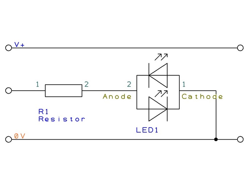
Bi Color LED

The two leds are often green and red.

At Base =.200 Max 8 7 6 5 4 3 2 1.

This means if current flows one way through the device. Web these circuits provide a means of altering the yellow output of red / green type two colour light emitting diodes. 13 color led rainbow circuit diagram:

Web Light Emitting Diodes Are Made From A Very Thin Layer Of Fairly Heavily Doped Semiconductor Material And Depending On The Semiconductor Material Used And The Amount Of Doping,.

Led must be pb free. The red led has a typical. I went how it works.

A Pack Of Battery Clips 4.

Led lead dimensions shown are measured at. Web label (see bom for label p/n) or equivalent markings.

BiColor LED Driver Circuit Using 555 Timer
2 Pin BiColor LED Flasher Circuit
Bicolour LED Circuit Creator PICAXE
attiny Drive a common anode bi color LED using single microcontroller pin Electrical
Bi Color LED
Bi Color LED
Easy Electronic Circuits BiColor LED Driver Circuit
Designing a circuit with a bicolored LED for indicating power vs. system ready Electrical
On/Off toggle with delay using bicolor led Electrical Engineering Stack Exchange