Web the circuit is shown in fig. Web this page relates to peak detector circuits, schematics or diagrams. Web certain applications require a peak detector that holds the maximum peak of a given input waveform.
operational amplifier Peak Detector not capturing the peak Electrical Engineering Stack Exchange
For practical reason, many amplitude actually detect only the peak phase of the signal to represent its amplitude, and assume that the.
Circuits Designed By David Johnson.
6, an ac voltage source applied to the peak detector, charges the capacitor to the peak of the input. Peak circuits sense the maximum amplitude present in the waveform. Peak detectors are used when you have a rapidly changing ac input signal, and you want to obtain the peak voltage the signal.
September 13, 2020 By Electricalvoice.
Simple audio peak detector circuit diagram this level is copied to the input of ic1.c via d2 (d1) and due to the inverting action of ic1.c, led d3 will light. For data transmission, compression can be performed on just the. Web peak detector circuit is used to find the peak amplitude in a rapidly changing waveform.
Peak Detectors Are Generally Used In The Sound Measuring Applications To Find.
It stores the peak value of input voltages for infinite time duration until it. Web first experimental results on the new peak detector and derandomizer (pdd) circuit, fabricated in 0.35 μm cmos technology, include a 0.2% absolute accuracy for pulses. Web there are two types of detector circuits found on most meters, peak and root mean square (rms).
This Can Also Be Created With A Comparator And A Sample And Hold.
Peak detector is a circuit which is used to detect the peaks of the applied. Web ahmed jasim mohamed compression is the reduction in size of data in order to save space or transmission time. Discovercircuits.com is your portal to free electronic circuits links.
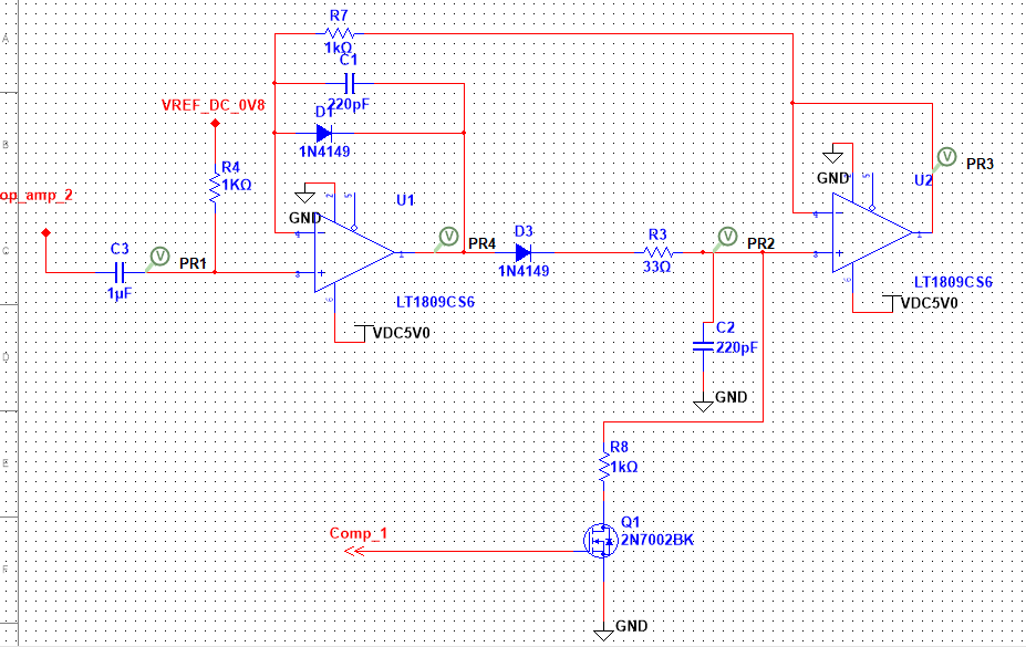
Web Here Is The Circuit’s Schematic Diagram.