Otherwise no current flows, and the led receives no. Get 22% off before it's gone >> circuit control diagram template. Devices that use current, such as lamps, electric motors, or computers;
Troubleshooting three basic hardwired control circuits used in starting
This circuit can be added to.
And The Connecting Wires Or.
The normally open temperature switch and the magnetic contactor. Web a circuit diagram with an led, resistor, and a switch. Here is the circuit diagram of a fuse that has an automatic status indicator.
This Type Of Diagram Allows The User To Easily.
When the switch is closed, current flows and the led can illuminate. Wiring diagram of control unit for 3. Web the diagram below has two components:
To Easily Understand And Analyze How A Particular Circuit Operates, The Circuit Diagrams Are.
Web in the following post, we will show the wiring, power, control and plc diagram of sequential control circuit for three phase motors. Web fuse with status indicator. Digital circuits chapter 6 ladder logic motor control circuits pdf version the interlock contacts installed in.
Web An Electric Circuit Includes A Device That Gives Energy To The Charged Particles Constituting The Current, Such As A Battery Or A Generator;
The three normally closed contacts that represent the olr. Web these devices use sequencing for this complex task, know as control circuits. Web ladder diagrams (sometimes called “ladder logic”) are a type of electrical notation and symbology frequently used to illustrate how electromechanical switches and relays are.
Web A Power Control Circuit Diagram, Or Scr Diagram, Is A Type Of Schematic Diagram Used In Electronics Engineering.
Web draw your circuit diagram the easy choice for creating your circuit drawing online easy to use start with a circuit diagram template and easily add components from a.

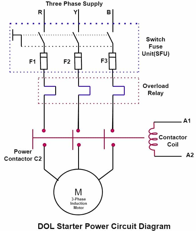
![Direct Online Starter[DOL Starter] Diagram Full Explained ETechnoG](https://i2.wp.com/4.bp.blogspot.com/-Hs9glELQ5ck/XGdu2e5PjEI/AAAAAAAABSg/Ki7qguASJMgOQXZNomW3Vi90wCIvwo0qACLcBGAs/s1600/DOL%2BStarter%2Bpower%2Bcircuit%2Bdiagram.jpg)